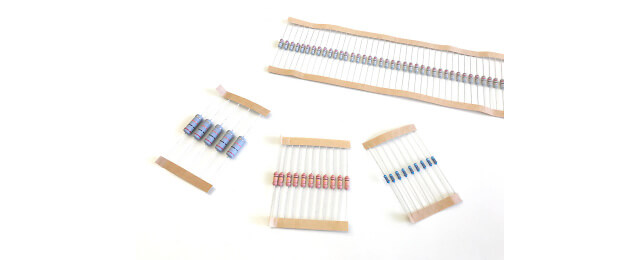
Wired resistors (THT)
Metal Film Resistors
Metal layer resistors have a thin layer of precious metal as a resistance material.
There are two variants for the production of metal layer resistors:
- Thick film technology
- Thin film technology
In the thick film technology process, precious metal layer is applied as a paste to a tempered glass carrier (usually ceramic) and burned in. The exact resistance value is achieved by scraping in spirals.
In thin-film technology, the precious metal layer is also burned onto a tempered glass carrier, but not as a paste, but it is evaporated through a mask.
Metal layer resistors are characterized by high accuracy (tolerance around 0.1%), low temperature coefficient and low resistance change, but also small powers. Such resistors are mainly used as precision resistors.

Carbon Film Resistors
Carbon layer resistors are particularly suitable in the high-frequency range, they usually have a rather small power 0.125W - 2W.
In addition, they are more likely to have a greater tolerance (5-20%). For this, coal layer resistors are a rather inexpensive variant.
The resistance values as well as the tolerances are indicated with color (for carbon layer resistors there are 3 or 4 rings).
Metal Film Resistors
Metal film resistors are resistors that use metal oxide as a resistance material and ceramic as a carrier material.
The metal oxide is evaporated onto the ceramic carrier. Then a silicone cement is applied to this metal oxide. This layer is very hard and mechanically almost indestructible. Since this layer is constructed like a tube and has no turns, these resistors are low in induction.
Metal oxide resistors can withstand overloads, high temperatures and other adverse environmental conditions.This technology mainly offers small high-load types for PCB mounting (guideline values: 0.5W to 5W), which are used, among other things, where high pulse loads can be endured (alternative to carbon and wire resistance). Compared to the carbon resistance, the tolerances are lower (guideline values 1% to 5%) and, unlike the wire resistance, higher resistance values can be produced.
Layer resistances are usually marked with 5 color coatings. The first 4 color rings indicate the resistance value in ohms. In the case of carbon layer resistance, there are usually only 3 color rings. The resistance value is given less precisely. The rearmost color ring provides information about the tolerance of the resistance.

Metal Electrode Leadless Face
Although they are much larger and more expensive than chip designs, MELF and Mini MELF packages continue to be produced and used.This is due, for example, to resistors because parameters such as pulse load capacity, temperature stability, long-term stability and dielectric strength as well as precisely specified behavior in the event of a fault (fuse resistance) are better achieved with MELF.
Thus, MELF resistors are mostly used where higher reliability and performance than normal SMD resistors are required.
MELF resistors are available in normal (MELF), small (Mini-MELF) and micro sizes (Micro-MELF).
MELF resistors have a cylindrical design like SMD components with two connections. The frontal surfaces are formed as contacts.
| Name | Dimension L × ⌀ | Power dissipation | Nominal voltage |
| MELF | 5,8 mm × 2,2 mm | 0,4 … 1 W | 350 V |
| Mini-MELF | 3,6 mm × 1,4 mm | 0,25 … 0,45 W | 200 V |
| Micro-MELF | 2,2 mm × 1,1 mm | 0,2 … 0,3 W | 150 V |


For the following resistances we ask you to contact us:
-
Resistors with fuse (Fusible Resistors)
-
Zero Ohm Resistors / Jumpers
-
Metal Glazed High Voltage Resistors
-
Special resistors